
Foldable Workshop Crane Design – Calculations, Forces and Real Engineering Approach
Introduction
Designing a foldable workshop crane may look simple at first glance: a boom, a hydraulic cylinder, a base frame.
In reality, this type of mechanism is highly geometry-dependent, and small changes in pivot positions or cylinder angle can dramatically increase required force and stress.
This guide explains:
- how forces actually work in a folding crane
- how to size the hydraulic cylinder
- what structural elements are most critical
- how to avoid the most common design mistakes
Why Foldable Cranes Are Tricky
A folding crane is not just a static beam.
You are dealing with:
- changing geometry during lifting
- nonlinear force distribution
- worst-case conditions at specific positions
👉 The key fact:
The highest load on the cylinder does NOT occur at maximum height.
It occurs at the lowest lifting position.
This is where most DIY designs fail. For other crane designs you need to change approach. We talk about Jib Crane Calculations or other lifting equipment like Lifting beam design (Traverse)
Crane Geometry – Define Your System First
Before any calculations, define your geometry.
Key parameters:
- L – boom length (pivot to load)
- a – cylinder attachment distance from pivot
- θ – boom angle
- α – cylinder angle relative to boom
- W – load (force)
Load and Moment Calculation
The fundamental equation is moment equilibrium around the boom pivot:

Where:
- W = load force
- L = distance from pivot
Cylinder Force Calculation
To balance this moment, the hydraulic cylinder must generate force:

Where:
- Fc= cylinder force
- a = lever arm of cylinder
- α = angle between cylinder and boom
⚠️ Critical Insight
When:
- α is small
- or cylinder is close to pivot
👉 required force skyrockets.
That is why low position = worst case.
Hydraulic Cylinder Sizing
Once you know required force, convert it into cylinder size.
Basic relation:

Where:
- p = hydraulic pressure
- A = piston area
From this:

Practical Example
If:
- required force = 40 [kN]
- pressure = 160 [bar]
Then:

Which gives a piston diameter of approx. 56–60 mm.
Structural Design Checks
The cylinder is not your only problem.
Real failures usually occur in:
1. Boom (bending)

Where:
- Wx = section modulus
2. Pins (shear)

3. Bolted joints
Check:
- preload
- shear + tension interaction
4. Buckling (compression members)
Long elements under compression can fail suddenly.
Boom Bending and Deflection
In a foldable hydraulic crane, the boom should usually be treated as a cantilever beam, not as a simply supported beam. The load acts near the free end of the boom, while the main support and pivot area behaves like a fixed support.
For a simplified cantilever boom with a point load at the end, the maximum bending moment is:
Mmax = P · L
Where:
- P – lifted load force
- L – distance from boom pivot to hook/load point
The bending stress in the boom can be estimated from:
σ = Mmax / Wx
Where:
- σ – bending stress
- Mmax – maximum bending moment
- Wx – section modulus of the boom profile
For a cantilever beam with a point load at the free end, the maximum deflection is:
fmax = P · L3 / 3EI
Where:
- fmax – maximum boom deflection
- E – Young’s modulus of steel
- I – second moment of area of the boom profile
If the load is applied at a distance a from the fixed support and the measured deflection is required at the free end of length L, the deflection can be estimated as:
f = P · a2 · (3L − a) / 6EI
For the common case where the hook is located at the end of the boom, a = L, and the equation simplifies to:
fmax = P · L3 / 3EI
This is why increasing boom length has a very strong effect on deflection. Doubling the boom length can increase deflection up to eight times if the same profile is used.
Folding Mechanism – Design Tradeoffs
Foldable design introduces additional challenges:
✔ Advantages
- compact storage
- mobility
- multi-position usage
X Tradeoffs
- lower stiffness
- more joints → more play
- higher stress concentrations
XLS Engineering Calculations – Real Design Tool
Instead of guessing or calculating everything manually, you can use a structured engineering model.
The calculation sheet typically includes:
- cylinder force vs angle
- boom moment distribution
- stroke calculation
- geometry-based position analysis
- safety factor evaluation
👉 This allows you to:
- test multiple configurations quickly
- validate design before CAD finalization
- avoid oversizing components
In the future, we will include lifting boom stress analysis in the CAD designs of our folding cranes.
Real Design Examples
Below are tested CAD projects based on this exact approach:
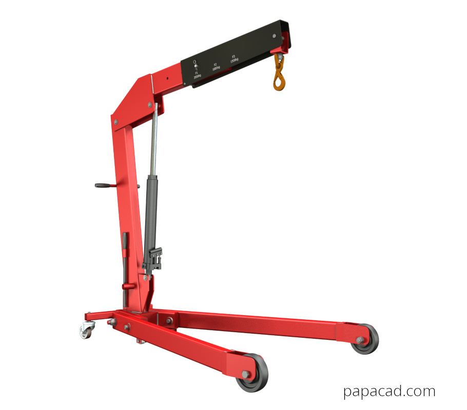
2000 kg Workshop crane CAD project
3D & 2D + XLS Calculations
From 19$
1100 kg Workshop crane CAD project
3D & 2D + XLS Calculations
From $19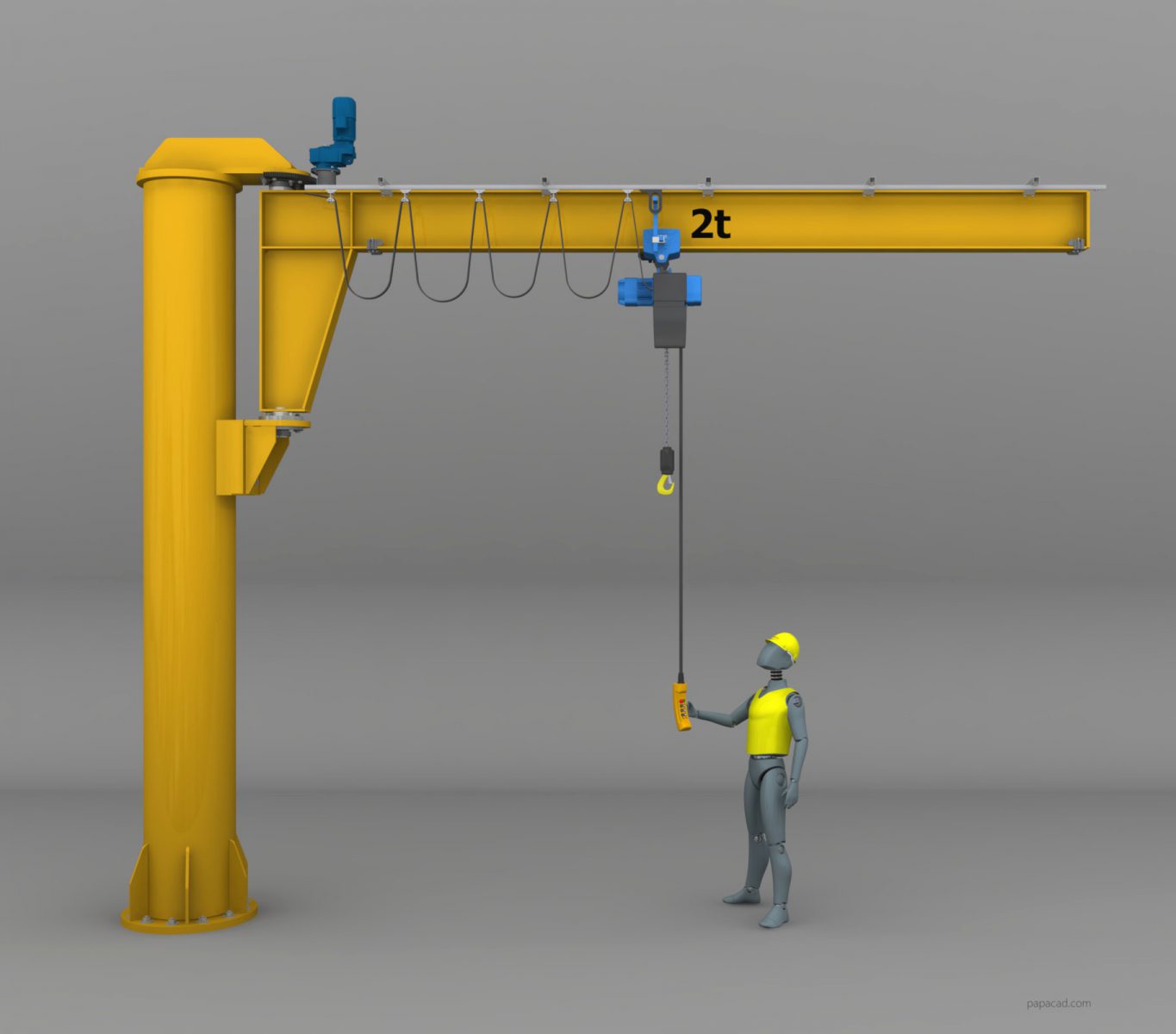
2000 kg Jib crane CAD project
3D & 2D CAD Designs
From $19These models include:
- full 3D assemblies
- production drawings
- engineering calculations (XLS)
Common Design Mistakes
Most failures come from:
- designing for one position only
- ignoring cylinder angle
- underestimating pin loads
- poor load path understanding
- no safety factor
Key Takeaways
- geometry defines everything
- worst-case = lowest position
- cylinder force depends on angle, not just load
- structural checks are mandatory
- engineering calculations save time and prevent failures
Final Thought
You can design a workshop crane by intuition.
Or you can design it as an engineer:
👉 based on geometry, force balance and verified calculations.