
Scissor Lift Force Calculation – Engineering Approach
What Determines the Force in a Scissor Lift?
A scissor lift looks simple, but the force required to lift a load is highly nonlinear.
The biggest mistake beginners make is assuming:
“Force = Load / 2”
That is wrong.
The required force depends mainly on:
- scissor angle (geometry)
- position of the cylinder
- load distribution
- friction and real-world losses
And the most critical factor is:
👉 the angle of the scissor arms
Why Force Increases at Low Angles
At the lowest position, the scissor mechanism is almost flat.
This creates a mechanical disadvantage:
- small vertical movement
- large horizontal force required
In practice:
👉 maximum force occurs at the lowest position
This is the worst-case scenario and must be used for sizing the hydraulic cylinder.
Basic Scissor Lift Force Relationship
The simplified force relationship can be expressed as:

Where:
- F = force in actuator
- W = load
- θ = angle of scissor arms
Visualizing the Geometry

What This Means in Practice
Let’s take a real example:
- Load: 1200 kg
- Angle: 10°

👉 The cylinder must generate almost 3x the load
The Real Problem: Geometry Is Not Constant
The equation above is simplified.
In real scissor lifts:
- cylinder is not centered
- pivot points shift
- arm lengths matter
- force changes during motion
So the real calculation must include:
- lever arms
- moment equilibrium
- cylinder mounting geometry
Cylinder Placement Changes Everything
Two identical scissor lifts can have completely different force requirements depending on:
- cylinder anchor position
- stroke length
- linkage configuration
👉 This is why copying a design without calculation is dangerous.
Engineering Approach (Correct Way)
To properly calculate scissor lift force:
1. Define geometry
- arm length
- pivot spacing
- cylinder position
2. Calculate moment equilibrium
Instead of simple force division, use:

3. Evaluate worst-case position
👉 usually minimum height
4. Add safety factor
- typical: 1.5 – 2.0
Common Design Mistakes
X Using average force instead of maximum
X Ignoring cylinder angle
X Assuming symmetric load
X Not checking lowest position
Real Engineering Insight
In many DIY designs:
👉 cylinder is undersized by 30–60%
This leads to:
- slow lifting
- system failure
- unsafe operation
Practical Tip
If you don’t want to calculate everything manually:
👉 use parametric calculations where you can input:
- load
- geometry
- lift height
and instantly get:
- required force
- cylinder stroke
- mechanical advantage
Ready-to-Use Engineering Solution
If you want to skip trial and error, you can use a complete CAD project with built-in calculations:
- full 3D model (Inventor)
- production drawings (DWG + PDF)
- ready-to-use Excel calculators (force, stroke, geometry)
👉 This allows you to:
- input your own parameters
- instantly verify design
- avoid costly mistakes
👉 Check the full scissor lift CAD project here:

1200kg Hydraulic Scissor Table Lift
3D & 2D Design + XLS Calculations
From $15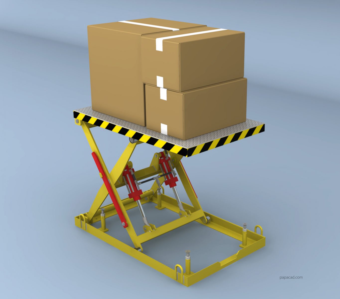
DIY 500kg Scissor Lift Table
3D & 2D Design + XLS Calculations
From $14
1000 kg Hydraulic Two Stage Scissor Lifter
3D & 2D Design
From $19Final Takeaway
Scissor lift force calculation is not trivial.
The key rule:
-> The lower the angle, the higher the force.
And:
-> Your cylinder must be sized for the worst-case position, not average load
If You Are Designing a Scissor Lift
Make sure you:
- calculate force at minimum height
- include real geometry
- verify cylinder capacity
- use safety factors
Or use a tested engineering model instead of guessing.