
Description
Screw conveyor design – 3D & 2D documentation
Download CAD documentation of screw feeder design with complete production CAD drawings and 3D assembly models
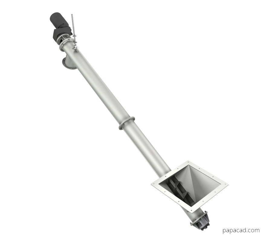
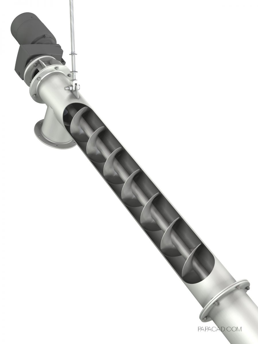
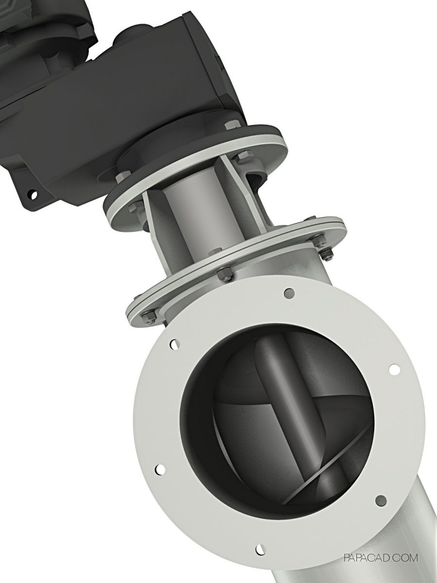
Screw conveyor for transport bulk materials such as gypsum, lime, cement, flour. Body is made of structural steel S355JR. Shaft and helix made of stainless steel 1.4301. Gear motor power 1,5[kW], maximum permissible output speed ~50rpm.
Screw feeder design has been created in Autodesk Inventor 2014. We have been prepared complete 3D CAD project and 2D drawings for production. You will be able to open all project CAD files in any of popular CAD systems like Inventor (version 2014 or higher), Solid Works, Solid Edge, PTC Creo, Catia and 3Ds Max or Rhino3D. Download CAD drawings and diy screw conveyor yourself.
Screw conveyor design description
- product for transport bulk materials such as gypsum, lime, cement
- electrical motor operating 1,5[kW]
CAD 3D Model & 2D DWG drawings documentation description
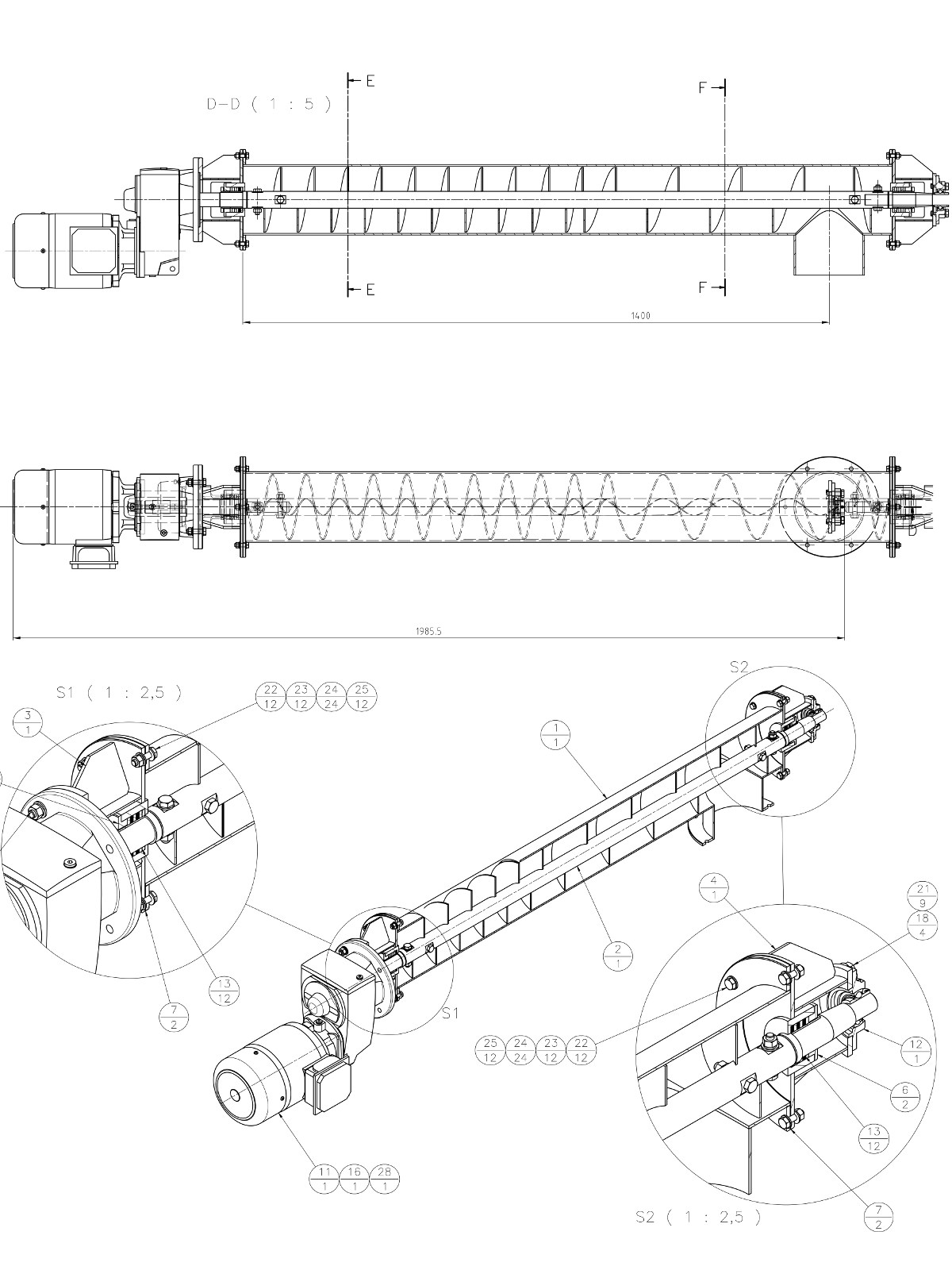
- 3D Inventor 2014 assembly – 62 3D solid parts and sheet metals( 207 subassemblies and parts occurences in active project)
- main assembly contains:
- 2D Inventor DWG assembly drawings – soon
- 3D STEP – 1 file
- 3D STL – 1 file
- 3D DWF – 1 file
- 2D DWG (2004) – soon
- 2D PDF – soon
Read more about our workshop engineering CAD projects →


Jose –
Can you please upload the 2d fabrication drawings?