

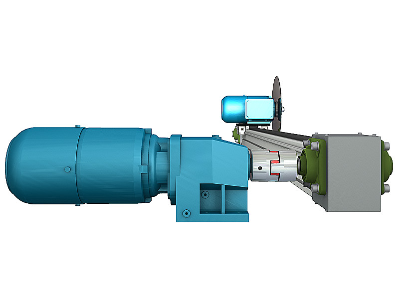
Disc Cutter Belt Drive – HTD Traverse Saw CAD Design
This disc cutter belt drive CAD design gives you the complete 3D STEP model of an industrial traverse saw mechanism built around a HTD toothed belt. Originally engineered for an automotive plant, the unit moves a disc saw carriage back and forth across a conveyor line to cross-cut foam and mineral wool mats between 0.5 and 5 cm thick. The carriage rides on paired steel guide rods, driven by an HTD belt wrapped around the full length of the beam, with the disc blade motor mounted directly on the moving carriage. Download the STEP model and see the complete belt, guide rod and carriage assembly.
HTD Belt Drive Mechanism Design Features
Traverse Saw Belt Drive CAD Model – Technical Specifications
| Disc blade material | NCV1 (80CrV2) tool steel |
| Blade diameter | 380 mm |
| Blade thickness | 2.6 mm |
| Blade rotation speed | ~1400 rpm (direct-coupled to motor, no reduction) |
| Belt drive | HTD toothed belt |
| Traverse drive | Geared motor, 1:2 ratio, via jaw coupling |
| Traverse stroke | 1.7 m |
| Traverse speed | 0–2 m/s |
| Material cutting thickness range | 0.5–5 cm (foam / mineral wool mats) |
| Guide system | 2× Ø10 mm steel guide rods, spherical bearing units |
| File formats included today | 3D STEP |
| In progress (not yet included | Native Inventor assembly, 2D DWG drawings |
Who Uses This Conveyor Line Cutting Machine Design
HTD Toothed Belt Drive CAD – Before You Build Checklist
This traverse saw mechanism fits naturally alongside our other conveyor-line and material-handling designs. See our Screw Conveyor CAD design for a related industrial material-transport mechanism, or browse our 3D CAD Engineering Designs category, or more industrial disc saw mechanism references. Also you can learn from our Engineering Guides.


Reviews
There are no reviews yet.